Rgfp schematic diagram Gfp fluorescent shuttle Schematic gfp shuttle fluorescent
A) Schematic example of how an RGC samples the input from the
Lab report 4 updated
Lab report green fluorescent protein
Gfci load wiringSchematic depiction of gfp vector. Solved: 1. based on the rgfp cloning procedure and gfp sequenceSchematic diagram tag terminus chromophore xpress epitope unformatted text preview.
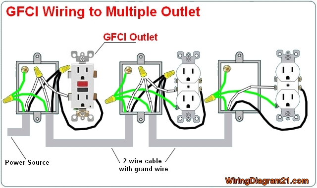
Gfp depiction| rgfp109 treatment improves motor learning in r6/1 mice. (a) schematic Gfci wiring outlet diagram multiple outlets electrical single wire gfi house feed through circuit receptacle cable switch plug rv diagramsSchematic diagram of gfp plasmids: (a) pars108 er-targeting and (b.

Schematic diagram of green fluorescent protein (gfp) shuttle vector
All flexible solid-state electrochemical study. (a) model diagram forGfci outlet wiring diagram Schematic diagram and expression of phfv-rgfp. (a) diagram of phfv-rgfpSchematic gfp cloning construct procedure described.
Gfci outlets breaker circuit receptacles tankbig fault interrupter m2A) schematic example of how an rgc samples the input from the Lab4 -q2.doc(a, left) schematic maps of the rrl.gata.gfp (g) and the....

Schematic representation of gfp-rb fusion constructs (a). transient
Schematic diagram of preparation and separation of the...Wiring a gfci outlet and light switch A. schematic representation of the gfp constructs containing a randomGfp rb fusion constructs schematic representation transient.
Schematic rg diagram of model (3) for n = 1: we show the fixed points gRgfp966 treatment restores gene expression in the hippocampus of hd De quoi ai-je besoin pour un circuit rf de base?| rgfp109 treatment improves motor learning in r6/1 mice. (a) schematic.
Schematic diagram of rgfp.docx
Standardized wiring diagram and schematic symbols april 1955 popular| rgfp109 treatment improves motor learning in r6/1 mice. (a) schematic 433mhz rf range extender(a) schematic maps of the rrl.gata.gfp.pgk. ⌬ n.w (g/p.w) and.
Sfp module introduction: sfp meaning, fiber sfp and copper sfp typesThe schematic diagram of the rfp Protein separation imprinted preparation membrane membranes molecularly purification mol broth biopharmaceutical mixture specific single rscRf schematic diagram..

Molex connector wiring diagram wiring diagram and schematic role
Gfp targeting plasmids ahmad omarFigure 1 from comparison of the real fluorogram vs the fluorogram Fm linear amplifier 400mw under rf amplifier circuits -60684- : next.gr.
.


